
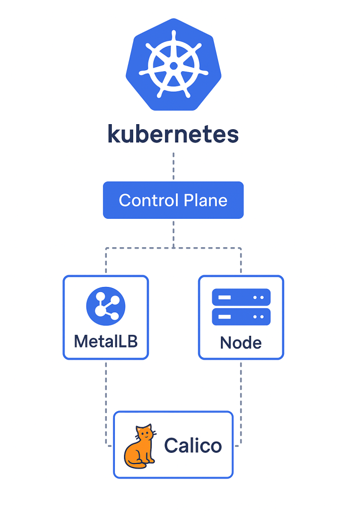
This guide helps to setup a kubernetes cluster with Metallb as a loadbalancer and Calico as the CNI.

Assumptions:
- 3 servers are available, one to be used as a Master node and the rest as Worker nodes.
- Access to use the public repositories. If not, a local repository is required.
1. Introduction to Container Orchestration and Kubernetes Architecture
Kubernetes, often abbreviated as K8s, stands as the ubiquitous, open-source platform designed to automate the deployment, scaling, and management of containerized applications. The fundamental power of Kubernetes lies in its architectural framework, built upon a desired state model. In this model, the system operator defines the desired configuration of resources—such as the number of application replicas, network accessibility, and storage persistence—and the Control Plane works relentlessly to inspect the current state of the cluster and enact changes necessary to reconcile it with the desired state.
1.1 Kubernetes Cluster Architecture: Control Plane vs. Data Plane
The Control Plane, usually running on one or more master nodes, is like the brain of the cluster. It keeps track of the cluster’s health and settings, decides where to run workloads, and makes sure everything stays in sync. Since this setup runs on bare metal instead of a managed cloud service like Google Kubernetes Engine (GKE), the Control Plane’s reliability—especially its data storage—is the most important factor for keeping things running long-term. Because of this, keeping a close eye on it is essential to avoid problems in such a centralized setup.
The Worker Nodes make up the Data Plane. These are the physical or virtual machines that actually run the applications. They do this by running Pods, which are small units that package up the containerized workloads.
1.2 Core Components of the Control Plane
The Control Plane orchestrates all cluster activity and relies on a collection of decoupled, yet interdependent, processes:
kube-apiserver: This component acts as the frontend for the entire Kubernetes control system. It serves as the unified endpoint for all administrative interactions, receiving and validating configuration requests (CRUD operations via REST), and ensuring that data is persisted in the backing storeetcd: The cluster’s singular source of truth.etcdis a highly available, distributed key-value store responsible for reliably storing the cluster’s configuration data and its current operational state. Any modification to the cluster state, whether creating a Deployment or scaling a replica set, must be recorded successfully inetcdvia thekube-apiserver.kube-scheduler: The scheduling process monitors the API Server for newly created Pods that have yet to be assigned a worker node. Based on complex constraints—including resource requirements (CPU, memory), node affinity, and policy restrictions—the scheduler selects the most appropriate node on which the Pod should execute.kube-controller-manager: This critical component runs various control loops that are continuously monitoring the state stored inetcdvia the API server. Controllers, such as the Node Controller, Replication Controller, and Endpoint Controller, are constantly adjusting the live state of the system to match the user’s desired state.
1.3 Core Components of the Data Plane (Worker Nodes)
Every machine dedicated to executing workloads hosts several essential components that facilitate communication and lifecycle management:
kubelet: The primary agent running on each worker node. Thekubeletensures that containers described in the PodSpecs received from the Control Plane are running and healthy. It maintains communication with the control plane, reporting the node’s resource status and managing the local container runtime- Container Runtime Engine (Containerd): This component is responsible for handling all container image operations, including pulling, running, and stopping containers based on instructions from the
kubelet. Modern Kubernetes deployments rely on Container Runtime Interface (CRI) compliant runtimes such as Containerd or CRI-O. kube-proxy: A network proxy that runs on every node. It maintains the necessary network rules, typically using iptables or IPVS, to facilitate communication between Pods and Services both internally within the cluster and externally, abstracting the complex networking layer away from application developers.
2. Preparing the Ubuntu servers
Setting up a Kubernetes cluster using kubeadm requires preparation of the operating system environment on all three servers (Control Plane and two Workers). Failure to align kernel parameters and the Container Runtime configuration will inevitably result in unstable core cluster component execution.
2.1 System Configuration and Kernel Tuning
Disabling Swap Permanently
Kubernetes explicitly mandates that disk swap memory must be disabled across all nodes to ensure predictable memory allocation and performance, preventing unexpected latency caused by system paging.
# 1. Temporarily disable swap for the current session:
sudo swapoff -a
# 2. Permanently comment out all swap entries in /etc/fstab to persist across reboots:
sudo sed -i '/\s+swap\s+/d' /etc/fstab
Loading Required Kernel Modules
The cluster requires specific Linux kernel modules to properly handle container-related networking functions, particularly overlay networks utilized by the chosen CNI (Calico). The overlay and br_netfilter modules enable container isolation and allow Kubernetes to correctly route bridged traffic.
# Add modules to load at boot
sudo tee /etc/modules-load.d/k8s.conf <<EOF
overlay br_netfilter
EOF
# Load modules immediately
sudo modprobe overlay
sudo modprobe br_netfilter
Enabling Kernel Networking Parameters
Critical network bridging parameters must be configured to ensure that kernel traffic forwarding is enabled and that traffic handled by the CNI bypasses default Linux network filtering mechanisms.
# Configure sysctl parameters for network forwarding and bridge-nf traffic management
sudo tee /etc/sysctl.d/k8s.conf <<EOF
net.bridge.bridge-nf-call-iptables = 1
net.bridge.bridge-nf-call-ip6tables = 1
net.ipv4.ip_forward = 1
EOF
# Apply sysctl parameters immediately
sudo sysctl --system2.2 Container Runtime Installation and Cgroup Configuration (Containerd)
Containerd is selected as the Container Runtime Interface (CRI) compliant engine. Its configuration must be precisely matched to the Kubernetes resource management model.
Installing and Configuring Containerd
The installation is followed by a non-trivial configuration step: aligning the container runtime’s cgroup driver with that expected by the kubelet. Kubernetes, by default, expects the systemd cgroup driver to manage Pod resource quotas and lifecycle. If the runtime uses a different driver (like the default cgroupfs), the kubelet will detect a mismatch, leading to resource misallocation and critical Control Plane components failing to initialize correctly (often seen as Pods remaining in a pending state).
# 1. Install Containerd and related tooling
sudo apt update
sudo apt install -y containerd.io cri-tools

# 2. Create the configuration directory and default config file
sudo mkdir -p /etc/containerd
sudo containerd config default | sudo tee /etc/containerd/config.toml

# 3. Modify config.toml to use SystemdCgroup = true
# This step is paramount for kubelet compatibility
sudo sed -i 's/SystemdCgroup = false/SystemdCgroup = true/' /etc/containerd/config.toml

# 4. Restart and enable Containerd to apply changes
sudo systemctl restart containerd
sudo systemctl enable containerd
Verification of the service status confirms operational readiness: sudo systemctl status containerd.
2.3 Installing Kubernetes Tools (kubeadm, kubelet, kubectl)
The core tools for cluster administration and bootstrapping are installed from the Kubernetes repository.
sudo apt-get update
sudo apt-get install -y apt-transport-https ca-certificates curl

# Download the Google Cloud public signing key
sudo curl -fsSLo /usr/share/keyrings/kubernetes-archive-keyring.gpg https://packages.cloud.google.com/apt/doc/apt-key.gpg
For environments connected directly to the internet, the standard repository is used.
# Add the Kubernetes APT repository source list (Internet Access Scenario)
echo "deb [signed-by=/usr/share/keyrings/kubernetes-archive-keyring.gpg] https://apt.kubernetes.io/ kubernetes-xenial main" | sudo tee /etc/apt/sources.list.d/kubernetes.list

sudo apt-get update
sudo apt-get install -y kubelet kubeadm kubectl
Using an Internal Repository (User Requirement):
If deployment mandates the use of an internal package mirror, the repository source list definition must be explicitly modified to point to the internal location, replacing the public Google APT endpoint:
# Alternative: Internal Repository Command
echo "deb [signed-by=/usr/share/keyrings/kubernetes-archive-keyring.gpg] http://INTERNAL_REPO_URL/apt/k8s kubernetes-xenial main" | sudo tee /etc/apt/sources.list.d/kubernetes.list

sudo apt-get update
sudo apt-get install -y kubelet kubeadm kubectl
Holding Package Versions
To prevent unintended minor or major version upgrades—which can introduce version skew and cluster instability—the installed Kubernetes packages must be explicitly held. This places the burden of coordinated, verified cluster component upgrades squarely on the administrator.
# Hold packages to prevent unintended upgrades
sudo apt-mark hold kubelet kubeadm kubectl
3. Cluster Initialization: Control Plane Setup (Master Node Only)
The primary master node (Control Plane) is now initialized using kubeadm. This process requires carefully planned network configuration to ensure compatibility with the selected CNI (Calico).
3.1 Network Planning and CIDR Allocation Strategy
In a bare-metal environment, network segmentation must be meticulously planned to ensure Pod IPs do not overlap with the existing host network infrastructure. The Pod Network CIDR must be known upfront and passed to the kubeadm initcommand for the chosen CNI to properly configure routing.
Table 1: Cluster Network Allocation Schema
| Network Type | Example CIDR | Function in Cluster |
| Pod Network (Calico) | 192.168.0.0/16 | IP space for individual Pods (internal cluster routing). |
| Service Network (ClusterIP) | 10.96.0.0/12 | Virtual IPs for internal communication between services. |
| LoadBalancer Pool (MetalLB) | 192.168.1.240-250 | Routable IPs provided by MetalLB for external access. |
3.2 Initializing the Control Plane Node
The kubeadm init command bootstraps the Control Plane, pulling required system images, deploying core components (API server, scheduler, etc.) as static Pods, and establishing cluster certificates. For Calico, specifying the Pod network CIDR is mandatory. The selection of 192.168.0.0/16 is a conventional choice for Calico documentation
# Execute kubeadm init on the Control Plane node
sudo kubeadm init --pod-network-cidr=192.168.0.0/16
The success of the initialization is typically followed by the output of the crucial node join command, which must be secured for later use.
Configuring kubectl Access:
The administrative credentials generated by kubeadm init are stored in /etc/kubernetes/admin.conf. These credentials grant cluster-admin privileges. To interact with the cluster as a regular user, the configuration file must be copied to the user’s home directory and permissions adjusted accordingly.
mkdir -p $HOME/.kube
sudo cp -i /etc/kubernetes/admin.conf $HOME/.kube/config
sudo chown $(id -u):$(id -g) $HOME/.kube/config
3.3 Installing the Calico Container Network Interface (CNI)
Immediately after initialization, the Control Plane is running, but CoreDNS and other Pods remain non-functional because they lack network connectivity. The master node will show a NotReady status until a CNI plugin, such as Calico, is deployed to establish the Pod network fabric. The approach here utilizes the Calico manifest, which deploys the calico-node DaemonSet and the calico-kube-controllers Deployment into the calico-system namespace.
# 1. Apply the Calico manifest using a stable release version
# Note: Ensure the version link points to the required stable release.
kubectl apply -f https://raw.githubusercontent.com/projectcalico/calico/v3.30.3/manifests/custom-resources.yaml

# 2. Monitor the deployment status of Calico pods
watch kubectl get pods -n calico-system
Once the CoreDNS and Calico Pods report a Running and 1/1 READY status, the foundational networking layer is operational, enabling inter-Pod communication and allowing the cluster to transition toward stability.
4. Worker Node Integration and Cluster Health Validation
With the networking foundation in place, the worker nodes can now safely join the cluster using the join command generated during Control Plane initialization.
4.1 Joining Worker Nodes to the Cluster (Worker Nodes Only)
The following command must be executed on both remaining Ubuntu servers, using the specific token and hash recorded previously.
# Execute the join command obtained from kubeadm init output:
sudo kubeadm join <ControlPlaneIP:Port> --token <token> \
    --discovery-token-ca-cert-hash sha256:<hash>
4.2 Cluster Status Verification
After allowing a few minutes for the kubelet on the worker nodes to complete TLS bootstrapping and register with the Control Plane, the cluster status is checked.
kubectl get nodesThe anticipated successful output confirms that both worker nodes (server-02, server-03) have registered and the Control Plane (server-01) is now fully connected and ready to accept workloads.
Expected Final Output (Post-Calico, Post-Join):
| NAME | STATUS | ROLES | AGE | VERSION |
| server-01 | Ready | control-plane,master | 10m | v1.XX.X |
| server-02 | Ready | 2m | v1.XX.X | |
| server-03 | Ready | 1m | v1.XX.X |
4.3 Removing the Control Plane Taint
By default, Control Plane nodes are tainted, meaning they are configured not to accept general user workloads. This is a crucial separation in large production clusters to preserve the stability of critical Control Plane processes. However, in small, resource-constrained clusters like this 3-node deployment, it is standard practice to untaint the Control Plane node to maximize resource utilization, allowing it to function as both a manager and a worker
# Remove the taint blocking workload scheduling on the Control Plane node
kubectl taint nodes --all node-role.kubernetes.io/control-plane-
The resulting allocation is a practical trade-off, balancing cluster resource availability against the stability guarantees provided by separating management and execution planes.
5. Integrating MetalLB Load Balancer (Layer 2 Mode)
Kubernetes Services of type LoadBalancer are natively supported only in public cloud environments where the cloud provider infrastructure automatically provisions an external IP. In a bare-metal installation, this functionality must be introduced manually by an external component. MetalLB fulfills this role by acting as a native LoadBalancer controller for on-premises deployments. The Layer 2 mode is chosen for its simplicity and minimal network requirements.
5.1 MetalLB Component Installation
MetalLB operates using two main components: the cluster-wide controller (responsible for IP allocation) and the per-node speaker (responsible for IP advertisement). The installation creates the necessary Custom Resource Definitions (CRDs) and deploys the components into the metallb-system namespace.
# 1. Apply the official manifest for MetalLB (using a stable version link)
kubectl apply -f https://raw.githubusercontent.com/metallb/metallb/v0.15.2/config/manifests/metallb-native.yaml

# 2. Verify component status
watch kubectl get pods -n metallb-system
Successful operation is confirmed when all controller and speaker pods show a Running status, typically one speaker pod per cluster node.
5.2 Configuring Layer 2 IP Advertisement
After installation, MetalLB remains idle because no IP ranges have been defined for assignment. Configuration involves defining an IPAddressPool (the range of external IPs MetalLB can manage) and an L2Advertisement (instructing MetalLB to advertise those IPs using Layer 2 protocols, primarily ARP).
It is critically important that the defined IP range is reserved exclusively for MetalLB and does not conflict with DHCP or other statically assigned host IPs on the physical network. If a conflict occurs, MetalLB’s reliance on ARP spoofing to advertise the Service IP can cause serious local network disruptions.
We use the reserved range 192.168.1.240-192.168.1.250 from the host network subnet.
Creating the Configuration Manifest (metallb-config.yaml)
# metallb-config.yaml
# CRD 1: Defines the pool of external IP addresses
apiVersion: metallb.io/v1beta1
kind: IPAddressPool
metadata:
  name: external-lb-pool
  namespace: metallb-system
spec:
  # Define the actual IP range available on your local network
  addresses:
    - 192.168.1.240-192.168.1.250
---
# CRD 2: Enables Layer 2 advertisement for the defined IP pool
apiVersion: metallb.io/v1beta1
kind: L2Advertisement
metadata:
  name: l2-advertisement-all
  namespace: metallb-system
spec:
  # Explicitly link to the IPAddressPool defined above
  ipAddressPools:
    - external-lb-pool
Applying the MetalLB Configuration
kubectl apply -f metallb-config.yamlOnce applied, the MetalLB controller can fulfill requests for Services requiring an external IP address.
6. Workload Deployment and External Access Validation
The final step is to validate the entire infrastructure stack—runtime, CNI, and load balancing—by deploying a sample application and exposing it externally.
6.1 Deploying a Sample Nginx Application
A simple Nginx deployment is created with two replicas.
# Deploy Nginx with two replicas
kubectl create deployment nginx-demo --image=nginx:latest --replicas=2
Expected Output:
deployment.apps/nginx-demo created6.2 Exposing the Application via a LoadBalancer Service
The Deployment is exposed via a Service object explicitly declared as LoadBalancer type. This triggers MetalLB to allocate an IP address from its configured pool.
# Expose the deployment on port 80, requesting a LoadBalancer type
kubectl expose deployment nginx-demo --type=LoadBalancer --port=80
Expected Output:
service/nginx-demo exposed6.3 Service Validation and Connectivity Test
Initially, retrieving the service details will show the EXTERNAL-IP as <pending>. This temporary state confirms that the cluster is waiting for an external controller (MetalLB) to fulfill the LoadBalancer request.
kubectl get svc nginx-demoMetalLB’s controller recognizes the pending Service and assigns the first available IP from the external-lb-pool (in this example, 192.168.1.240).
Example Command and Final Expected Output Table:
kubectl get svc nginx-demo
NAME TYPE CLUSTER-IP EXTERNAL-IP PORT(S) AGE nginx-demo LoadBalancer 10.96.100.5 192.168.1.240 80:30001/TCP 1m
MetalLB successfully allocated and advertised the external IP address from the configured Layer 2 pool.
This IP transition from <pending> to assigned confirms the full integration of MetalLB into the Kubernetes API lifecycle.
6.4 External Connectivity Test
The final step validates end-to-end connectivity by accessing the assigned external IP address from a machine located on the same host network segment. This confirms that traffic successfully traverses the physical network, is intercepted by the MetalLB speaker via ARP manipulation, routed through the cluster’s network fabric (Calico), and finally delivered to the running Nginx Pod via kube-proxy rules.
# Test connectivity using the external IP provided by MetalLB
curl http://192.168.1.240
Expected Output: The command returns the standard HTML source code for the Nginx welcome page, signifying a fully functional, self-hosted Kubernetes cluster.
7. Conclusions and Operational Synthesis
The process of building a Kubernetes cluster from scratch using kubeadm is fundamentally an exercise in managing dependencies across kernel parameters, container runtimes, CNI providers, and service layer extensions.
The successful integration of Calico and MetalLB hinged on mandatory precursor steps. Specifically, the configuration of the Containerd runtime to use the systemd cgroup driver proved essential for core component stability, while aligning the Pod CIDR during kubeadm init was necessary for Calico’s proper routing establishment. Furthermore, the selection of MetalLB’s Layer 2 mode addressed the key limitation of bare-metal deployments—the lack of native load balancing—by dynamically assigning and advertising a host-network IP range using Custom Resource Definitions.
The final validation test confirms that all disparate components, from kernel module loading to external IP advertisement, function collectively within the declarative ecosystem of Kubernetes. This detailed, manual configuration provides the administrator with comprehensive control over the cluster’s operational environment, necessitating meticulous adherence to prerequisite steps to ensure long-term stability and performance.